Mac's YJ build with tons and 42's.

View attachment 404792View attachment 404793View attachment 404794View attachment 404795

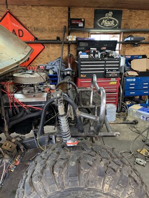
This is how I’m measuring and locating points for drawing my truss.

There are several DXF both free and paid on the web that are definitely just too generic and needed customizing for my constraints.

Once I realized anything on the market would need to be customized,

I decided I’d rather do most of the work in cad rather than with a grinder.

The idea is that the truss needs to hit the axle tube just before tangent so that the edge of the weld is close, but just above the centerline.

I took a lot of time making sure I could draw two lines on the axle that are where the front and rear vertical pieces of the truss will hit the housing. Making sure these lines represent two parallel planes.

Also had to make sure the locations from the front piece to the rear piece are identical in terms of left right and height. This is because these two plates and where they intersect the housing are very different.
How'd you draw that red line so straight?
 
IMG_3748.jpeg
IMG_3749.jpeg
IMG_3750.jpeg


Inside welded out, ready to weld onto the axle.

After it’s welded to the axle inside and out, I’ll then put the top piece back on.
 
I cut short lines to mark the bend locations.

Then I bend in my pipe Kinker with two pieces of angle iron welded to some plates to make a little hand brake for bending.

Then I just hammer or clamp in vise to fine tune the bend to match the profile.

Instead of trying to hit all the locations in one piece I just make it in sections so if any were wrong, I can cut/grind by hand or even recut just a section. But despite my best attempts to get it wrong, it fit great with minimal editing
 
I thought these were cool angles.

You can see where the weld area is despite being cleaned up, but the light has to be just right.

This is where the bump stops will hit on the truss and is also why I added internal plates to strengthen these two specific areas.

View attachment 405159View attachment 405160
Looks like cut and etch.....weld metal density just buffs different!
 
Axle back under jeep.

Currently located near but not perfect final location. @3.5” up in pics, need to get to 7” up min, maybe 8 depending on steering and crank pulley clearance.

Radiator may be a problem.

This gets me close enough to start working on the full hydro ram and tie rod locations.

Then figure out the radiator interference.

Only had a few minutes to work on it this weekend as life keeps throwing me curveballs.

Still more progress than D-6.

Front frame rails are in but not fully welded. Going to tie the reinforcement plates into the bump stop mounts.

Also going to cut off any extra from in front of the winch, so there is no extra tube hanging off the front.

Thinking of incorporating a tube for sway bar install if needed.

Mainly needed to get something back in to support the grill so I could slide axle back in with stands out of the way.
 
deets on those little blue radiator bushings? And why the double plate?
IMG_5050.png


These install in 11/16” hole and use a 3/8 bolt.

I swapped the factory 1/4” j nuts in the grill/rad support for 3/8 ones.

I figured if they can take the heat of being and exhaust hanger bushing, they’ll handle the radiator temps. Just didn’t want to fully solid mount the radiator with my brackets welded to the tanks directly. We will see how long it takes to crack the core/tank 🤣.

As far as the double plates, I hate fixing egg shaped holes and in the past I’ve had good luck with laminating 1/8” on top of .188” and not develop egg shape holes. Typically I just make a teardrop shape.

Honestly, I didn’t feel like swapping sheets on the plasma tables so I just did two layers of .188”.

Same for the design, I was being lazy and just offset the tab itself to make the double plate.

After fixing my dad’s elongated holes in his 1/4” plate tabs, ( which was a major pita) I started doing this with great results.

I also like getting the weld around the doubler plate to help strengthen it vs just a single solid basic tab.
 
Haven’t cut these yet as I’m going to switch material on the table, but these “worms” catch and guide the shock eye spacers into their “home”. These can be cut at not more than .125” thick material safely, as long as the misalignment thru travel is low, and static angle installed is in the center of misalignment.

Ideally I’ll cut these out of thinner to allow more shock eye clearance, I’ll have to see what I have in the stack.

With running the smaller 2.0 bodied shocks, that have smaller -8 uniballs, the typical installed width is 1.25” and the spacers sit outside the uniballs.

This makes installation tedious compared to 2.5” and larger shocks that use the bigger -10 uniballs and have misalignment spacers that fit inside the ball rather than beside it.

So I drew these up to weld inside the shock tabs to make installing the shocks a breeze.

Wide enough so that the spacers can’t fall out either side and just enough room to install by sliding the bolt thru the assembly.
IMG_5129.jpeg


This other one does the same task but is for the lower link. It welds inside the mounting tabs and guides the heim to line up perfectly with the bolt hole.

Typically by myself is a pita to install a link and get the bolt through with one hand and holding the link with the other.

Same idea as for the shock spacers to make install and service easier.

IMG_5130.jpeg
 
Back
Top