Somthing

I've never heard of this done before, I'm also curious about the drivetrain setup. Are there any links to other builds of this nature?
 
You're saying a transmission will go between the motor and that transaxle? Just curious and a little confused about it
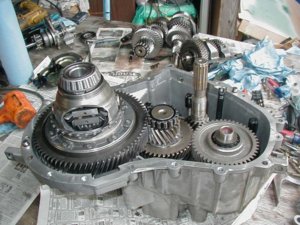
No.. He's using the transaxle as a combined transmission and pseudo-transfer case, albeit one that's stuck in "low range" all the time.
 
Ahh! that's makes way more sense! How's the driveshaft connect to the transaxle? home brew male SYE?
 
I am not paving any new paths with this overall transaxle concept. You should check out Tacoma747 buggy build, his is using a Honda engine/transaxle setup. Or if your interested search pirate4x4 your apt to find the most there.. That said I hope that I am able to put my own unique ideas into this and make it slightly different than whats out there...

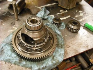
Here is a pic of the insides of the transaxle. Its a transmission (shafts on the right side) AND carrier/center section (see carrier on left) all mashed into one. (note: NOT MY PIC... found on the web)

P1010113_2.jpg

As said the down side is your using the final drive (aka carrier/ring gear) ratio ALL THE TIME. Sorta like being in low range ALL THE TIME. I think with the available final drive ratios and axle (toyota) ring/pinion choices I should be able to adjust it as needed....
 
I guess I need to indicate what my goals are with this so people can understand 'why' I'm doing one thing vs something else...
  • Low Budget $6,000 MAX to hit the trails able to wheel..
  • Simple/Minimal design
  • Light weight / Minimalistic - Shooting for <3000#
  • Functionality/Off-road ability

Yes I fully realize light weight and low budget don't usually go together but my plans are to use good parts selection and overall minimalistic design to aid. Along with extreme part/component reuse.
Tying in the transaxle component above. That F23 weights 107# wet and that's a pretty solid designed case/unit. Its designed to hold up to more torque than the motor makes and move a 4000# car.
Tying in budget, that one component will be the trans and ~t-case with low range/reduction 'built in' and these components are available from several low end (cheep) cars.

Suspension - Air shocks, 3 links, w/panhard, for tighter packaging.
Shafts - ya prolly modify a CV into a flange or find something to use...
No-rear steer :( Rather not stress the budget, add weight, or complexity.
Full hydro - simple, fewer components, and proven.

So far just a lot of sketches and drawing with some junk piled in the garage...
 
Yes I fully realize light weight and low budget don't usually go together

Hell yeah they do! You cant afford to buy it = it doesnt go on the rig = it doesnt weigh anything!


Most of adding lightness is free, anyways. Cutting holes, grinding unnecessary metal from brackets, running your cables as short as possible, etc., etc.

Nothing wrong with being locked in low range. Most buggies I know of are usually left in low range all the time, anyways.
 
The 'ring' gear in that transmission is HUGE compared to a honda trans. I haven't calculated my speed @ ~1000 rpms, honestly it's been too long since I've hit the trails,I don't remember what a good crawl speed is :)

I haven't added mine up in awhile, but I am using lots of "nice" parts (mostly used race car parts) that would normally be VERY high dollar items ($1000 + brake pedal system for $190), but I figure with everything I will definetly be under $10K, probably closer to $7-8K

A race for ages and ages, thanks JC :)
 
Quick update - Done a lot of bookwork crossing part numbers and such.

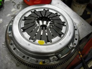
I got a brand new flywheel and clutch off craigslist. The clutch/disk are from an s10 but i'm hoping to find a disk that will work in that setup. I still need to verify that there aren't any issues with the throw out bearing etc.. I didn't think $40 was to bad, came with the bolts to bolt it on too :)

20090615-NewFlywheel01.jpg

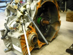
I got my transaxle tonight. It's a Getrag F23 5 speed. Cost me more to freight it than to buy it. But oh well it was cheep on ebay $99 for the trans, w/ 47k on it. Its clean and the T/O setup is in good shape. Plus how they cut everything works out nice. I will be able to make an AN adapter with the clutch fitting after i cut the plastic line off.

20090615-F23-02.jpg

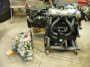
Here's sorta a pic of it next to the engine for size..
I lied it measures 13.5" from bell to the end. Hopefully I can still make it fit :flipoff2: Looks like I'm definitely doing rear engine, so that will be cool. Still lots of small things to ponder. Chase at East Coast Gear Supply was nice enough to loan me a used D30 carrier. Mainly wanted to compare that to the F23 unit. It uses the same carrier bearings so I was curious as to how similar they are dimensionally. Seems to be ~1" shorter. I need to check the spiders etc once I crack the transaxle open.
20090615-BuggyParts 009.jpg
 
Few more of the transaxle.. Need to get the mount for it, and a shifter but nothing thats holding me from moving forward.. Next step is to get some seats, so i can start some preliminary cage design/mock up..

20090615-F23-03.jpg

20090615-F23-04.jpg

20090615-F23-05.jpg
 
What if you put brakes on both outputs and used them like tractor brakes except front/rear? I would think that most of the time you would never need them, but you could modulate front dig rear dig. Kinda sleepy, may just be a stupid idea.
 
prolly a (toy)e-locker upfront.. guessing it will be the best/cost effective overall...

--- Thats sorta why i wanted to see what the d30 parts looked like to see if there was anyway maybe an ox or something 'might' fit into the transaxle. ill size it up more when i get it apart.. something might jump out at me when i see all the parts :)
 
What if you put brakes on both outputs and used them like tractor brakes except front/rear? I would think that most of the time you would never need them, but you could modulate front dig rear dig. Kinda sleepy, may just be a stupid idea.
That wouldn't work if he locks the diff inside the transaxle.
Looks like I'm definitely doing rear engine,
Does the direction the axle/driveshafts turn determine front or rear engine? Don't know why i even thought of that, but it would suck to build a badass buggy with 5 reverse gears and 1 forward.
 
I meant instead of locking the "center" diff, then it would have much less bind. What would really be cool is a chipped abs brain that could apply braking force in relation to shaft speed differential like the yaw control on newer performance cars. Open and very driveable most of the time and selectable slip in the hard stuff. Thinking out loud in case someone knows how to hijack an abs brain.
 
Does the direction the axle/driveshafts turn determine front or rear engine? Don't know why i even thought of that, but it would suck to build a badass buggy with 5 reverse gears and 1 forward.
Doesn't matter. Just figure out which way it turns and orient the differentials accordingly. (upside down or not)

Maybe you'll get lucky and you can run a low pinion E-locker upside down in the front to avoid the $$ of a Hi-Pinion.:driver:
 
axles will be flipped 'upside down'

I'll be hitting up you big time guys for some input on where to get some of the small items i'll need machined up etc.. I'm a long ways off from that but i'd be nice to find someone in NC who could handle it..

At this point I'd love to just have a spool made up, call it good...
but if thats not possible/feasable (cost) then someone who can cut/machine the half shaft cups and make them into a flange to mate a toy flange to...

anyone know of a good machinist/engineer type who might possibly want to help me with an idea to make an internal disconnect..
 
Tim williams @ Midstate machine in Mt. Ulla. He has designed several gear boxes for Leeboy equipment he may be able to help you.
 
"Budget build" and "Machine shop" don't go together very well.

Well...unless you already have the machine shop I guess...

There's already a couple proven drive-line disconnects on the market. Weld it up and buy two of those. Maybe?
 
rear engine... will be 2 seater, working on a staggered seating layout so driver is forward of the passanger enough to not be banging elbows and possibly pull em in closer together..

I'm thinking first pass will be to weld it up, modify the 1/2 shaft cups, and use a elocker up front, to allow for maneuvering. (plan to have lockright out back) Lots of stuff to get done, one piece at a time..
 
split the transaxle case to pull the carrier out. Next up is to figure out what I can do..

Its ~6.5" diameter and less than 10" long, a spool would be trick...

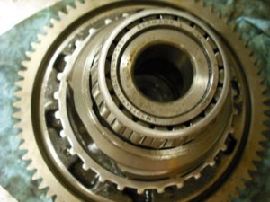
Not very please with the bearings inside everything looks good but I can see why guys have trouble with them around 100k. I'll probably replace the carrier bearings as those cause the most trouble and lead to other things to fail..

Anyone know how the output disconnects attach to the output shaft? Thinking if I could include that part into anything I end up doing.

20090616-F23 002.jpg

20090616-F23 007.jpg
 
If you mean how do the CV shafts stay in the trans ? "cir-clip's" hold the splines into the inside of the side gears. remember, they just " POP" out when you need to replace the CV shaft. A gracious nudge with a pry bar on the inner cup is all it takes.
 
huuh? yes i've popped 1/2 shafts out.. ? No I don't want to rely on that clip to hold a shaft/flange in the trans. I know they pop out, I'd like to use a toy flange directly on the outputs or carrier (or new spool)
 
Back
Top